The Scientist and Engineer's Guide to
Digital Signal Processing
By Steven W. Smith, Ph.D.
Book Search
Table of contents
- 1: The Breadth and Depth of DSP
- 2: Statistics, Probability and Noise
- 3: ADC and DAC
- 4: DSP Software
- 5: Linear Systems
- 6: Convolution
- 7: Properties of Convolution
- 8: The Discrete Fourier Transform
- 9: Applications of the DFT
- 10: Fourier Transform Properties
- 11: Fourier Transform Pairs
- 12: The Fast Fourier Transform
- 13: Continuous Signal Processing
- 14: Introduction to Digital Filters
- 15: Moving Average Filters
- 16: Windowed-Sinc Filters
- 17: Custom Filters
- 18: FFT Convolution
- 19: Recursive Filters
- 20: Chebyshev Filters
- 21: Filter Comparison
- 22: Audio Processing
- 23: Image Formation & Display
- 24: Linear Image Processing
- 25: Special Imaging Techniques
- 26: Neural Networks (and more!)
- 27: Data Compression
- 28: Digital Signal Processors
- 29: Getting Started with DSPs
- 30: Complex Numbers
- 31: The Complex Fourier Transform
- 32: The Laplace Transform
- 33: The z-Transform
- 34: Explaining Benford's Law
How to order your own hardcover copy
Wouldn't you rather have a bound book instead of 640 loose pages?Your laser printer will thank you!
Order from Amazon.com.
Chapter 16: Windowed-Sinc Filters
To design a windowed-sinc, two parameters must be selected: the cutoff frequency, fc, and the length of the filter kernel, M. The cutoff frequency is


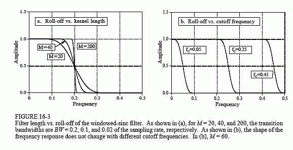
where BW is the width of the transition band, measured from where the curve just barely leaves one, to where it almost reaches zero (say, 99% to 1% of the curve). The transition bandwidth is also expressed as a fraction of the sampling frequency, and must between 0 and 0.5. Figure 16-3a shows an example of how this approximation is used. The three curves shown are generated from filter kernels with: M = 20, 40, and 200. From Eq. 16-3, the transition bandwidths are: BW = 0.2, 0.1, and 0.02, respectively. Figure (b) shows that the shape of the frequency response does not depend on the cutoff frequency selected.
Since the time required for a convolution is proportional to the length of the signals, Eq. 16-3 expresses a trade-off between computation time (the value of M) and filter sharpness (the value of BW). For instance, the 20% slower roll-off of the Blackman window (as compared with the Hamming) can be compensated for by using a filter kernel 20% longer. In other words, it could be said that the Blackman window is 20% slower to execute that an equivalent roll-off Hamming window. This is important because the execution speed of windowed-sinc filters is already terribly slow.
As also shown in Fig. 16-3b, the cutoff frequency of the windowed-sinc filter is measured at the one-half amplitude point. Why use 0.5 instead of the standard 0.707 (-3dB) used in analog electronics and other digital filters? This is because the windowed-sinc's frequency response is symmetrical between the passband and the stopband. For instance, the Hamming window results in a passband ripple of 0.2%, and an identical stopband attenuation (i.e., ripple in the stopband) of 0.2%. Other filters do not show this symmetry, and therefore have no advantage in using the one-half amplitude point to mark the cutoff frequency. As shown later in this chapter, this symmetry makes the windowed-sinc ideal for spectral inversion.
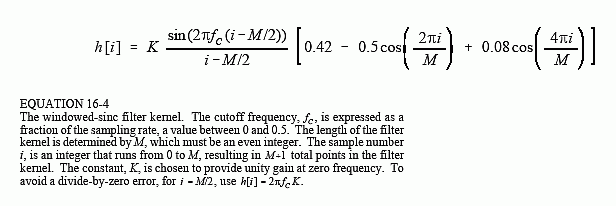
After fc and M have been selected, the filter kernel is calculated from the relation:

Don't be intimidated by this equation! Based on the previous discussion, you should be able to identify three components: the sinc function, the M/2 shift, and the Blackman window. For the filter to have unity gain at DC, the constant K must be chosen such that the sum of all the samples is equal to one. In practice, ignore K during the calculation of the filter kernel, and then normalize all of the samples as needed. The program listed in Table 16-1 shows how this is done. Also notice how the calculation is handled at the center of the sinc, i = M/2, which involves a division by zero.
This equation may be long, but it is easy to use; simply type it into your computer program and forget it. Let the computer handle the calculations. If you find yourself trying to evaluate this equation by hand, you are doing something very very wrong.
Let's be specific about where the filter kernel described by Eq. 16-4 is located in your computer array. As an example, M will be chosen to be 100. Remember, M must be an even number. The first point in the filter kernel is in array location 0, while the last point is in array location 100. This means that the entire signal is 101 points long. The center of symmetry is at point 50, i.e., M/2. The 50 points to the left of point 50 are symmetrical with the 50 points to the right. Point 0 is the same value as point 100, and point 49 is the same as point 51. If you must have a specific number of samples in the filter kernel, such as to use the FFT, simply add zeros to one end or the other. For example, with M = 100, you could make samples 101 through 127 equal to zero, resulting in a filter kernel 128 points long.

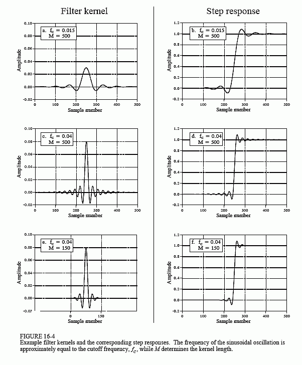
Figure 16-4 shows examples of windowed-sinc filter kernels, and their corresponding step responses. The samples at the beginning and end of the filter kernels are so small that they can't even be seen in the graphs. Don't make the mistake of thinking they are unimportant! These samples may be small in value; however, they collectively have a large effect on the performance of the filter. This is also why floating point representation is typically used to implement windowed-sinc filters. Integers usually don't have enough dynamic range to capture the large variation of values contained in the filter kernel. How does the windowed-sinc filter perform in the time domain? Terrible! The step response has overshoot and ringing; this is not a filter for signals with information encoded in the time domain.
